Appearance
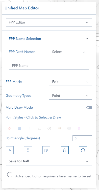
FPP Editor
Overview
The Forest Practices Plan (FPP) Editor is a comprehensive professional forestry planning system that provides advanced spatial editing capabilities for creating, managing, and processing forest operation plans. This sophisticated tool integrates ArcGIS drawing tools with specialized forestry workflows, supporting complete FPP lifecycle management through four distinct operational modes (Edit, Auth, Vary, Revoke) with extensive symbolic libraries, advanced geometric operations, and intelligent layer management for professional forestry planning applications.
Key Features:
- Multi-Mode Workflow System: Four distinct operational modes (Edit, Auth, Vary, Revoke) for complete plan lifecycle management
- Extensive Forestry Symbol Library: 50+ specialized forestry icons and symbols for points, lines, and polygons
- Advanced Permission Integration: Role-based access controls with FPP Admin and FPP User privilege levels
- Dual Layer Management: Separate draft and production layer systems with automatic layer group creation
- Professional Drawing Tools: ArcGIS drawing tools integration with coordinate transformation and union operations
- Integrated Advanced Editor: Built-in geometric operations including buffer, union, intersect, and difference
- Dynamic Style Management: Real-time style application with extensive customization options
Getting Started
Opening the FPP Editor

- Look for the Unified Editor icon (pencil) on the right toolbar
- Click the icon to open the editor panel
- Select FPP mode from the mode selector at the top
Permission Requirements
- Edit Mode: Basic access for creating draft plans
- Auth/Vary Modes: Requires appropriate planning permissions
- Revoke Mode: Restricted to FPP administrators only
INFO
If you don't see the FPP options you need, contact your GIS administrator about permissions.
Layer Management
Setting Up Layer Names
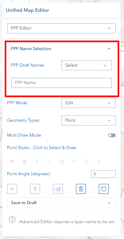
The FPP Name Selection accordion at the top contains all name and filter controls. The content of this section changes based on the current FPP mode:
- Edit mode: Shows a names dropdown (draft names) + text field to type a new name
- Auth mode: Shows a draft names dropdown + FPP Number field
- Vary mode: Shows a production names dropdown + Variation Name field
- Revoke mode: Shows a production names dropdown + Revoke Layer Name field
Before you can draw, you need to set a name:
- Use Dropdown: Select an existing FPP name from the list (refreshes on click)
- Type New Name (Edit mode only): Enter a new FPP plan name in the text field below the dropdown
- Wait for Activation: Drawing tools become available once a name is set
The system automatically creates appropriate draft and production layer groups for your geometry types when you provide a layer name.
Filter by Name
The Filter by Name toggle restricts the map display to features belonging to the selected FPP name:
- Select an existing name from the dropdown
- Toggle Filter by Name on
- The map immediately filters to show only features with that name (draft layers in Edit/Auth mode, production layers in Vary/Revoke mode)
- Toggle off to show all features
WARNING
The filter only responds to names selected from the dropdown. Typing a name in the text field (Edit mode) enables drawing but does not apply the filter.
TIP
While the filter is on, changing the dropdown selection automatically re-applies the filter to the new name.
FPP Modes
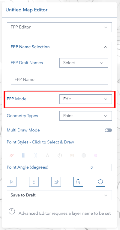
Edit Mode
Purpose: Create and modify draft FPP plans
- Full drawing and editing capabilities
- Access to all forestry symbols
- Save to draft layer system
Auth Mode
Purpose: Authorize draft plans to production
- Select existing draft plan
- Enter production FPP number in format
AAA0000(3 letters + 4 digits, e.g.ABC1234), optionally followed by_VARor_VAR1 - Convert draft to official production plan
Vary Mode
Purpose: Create variations of existing production plans
- Select production plan as base
- Enter variation name in format
VARorVARfollowed by a number (e.g.VAR,VAR1,VAR2) - The system combines the production FPP number with the variation name as
{FPPNumber}_{VariationName}(e.g.ABC1234_VAR1) - The combined name must be unique — it cannot already exist in FPP Production
- Create modified version while preserving original
Revoke Mode (Admin Only)
Purpose: Revoke production plans
- Available to administrators only
- Select production plan to revoke
- Enter revoke layer name in the same format as Auth FPP Number (
AAA0000) - Create revoked plan record
INFO
Mode selection automatically resets the interface and loads appropriate layer groups.
Geometry Types
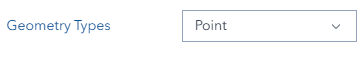
Choose the geometry type that matches what you want to create:
Point Features
- Best for: Equipment locations, crossings, gates, cable settings
- Examples: Landing areas, bridges, control points
Line Features
- Best for: Boundaries, roads, extraction routes, constraints
- Examples: Contractor boundaries, located roads, drainage lines
Polygon Features
- Best for: Areas, zones, boundaries, constraints
- Examples: Harvest boundaries, exclusion zones, FPP boundaries
Style Selection
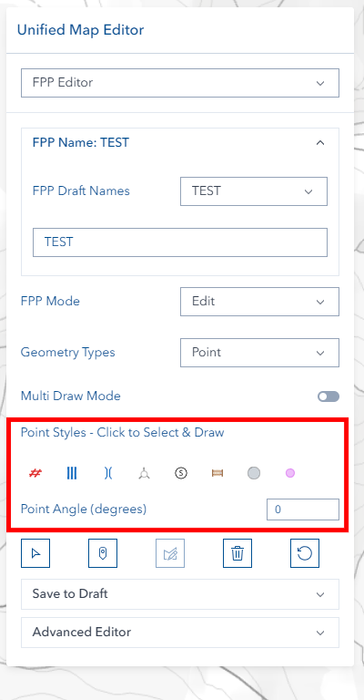
Choosing Styles
- Set your layer name first (styles are disabled until you do)
- Select your geometry type (Point, Line, or Polygon)
- Click on any style icon to select it
- The selected style will be highlighted
Point Styles
| Icon | Style Name |
|---|---|
| Landing | |
| Crossing | |
| Bridge | |
| Cable Setting | |
| Special Point Feature | |
| Text Point | |
| Not Coded |
Line Styles
| Icon | Style Name |
|---|---|
| Section Boundary | |
| Extraction Track | |
| Planned Road | |
| Scrub Roll Boundary | |
| Continuous Landing | |
| Linear Constraint | |
| Linear Constraint1 | |
| Surveyed Tenure Boundary | |
| Machinery Exclusion Zone | |
| Label Line | |
| Black Arrow | |
| Marked Boundary | |
| Eagle Management Zone | |
| Not Coded |
Polygon Styles
| Icon | Style Name |
|---|---|
| FPP Boundary | |
| Harvest Boundary | |
| Machinery Exclusion Zone | |
| Vegetation Constraint | |
| Hazard | |
| WTE exclusion zone | |
| Constraint | |
| Constraint1 | |
| Constraint2 | |
| Constraint3 | |
| Not Coded |
Special Options
Point Angle: For directional point symbols, enter a rotation angle (0–359 degrees). The angle resets to 0 when you switch to the Point geometry type.

Text Options: A Display Label and font size (8, 10, 12, 15, 20, 30 pt) are shown for the following styles:
- Text Point — label is optional; displayed on the map at the point location
- Label Line — label text displayed along the line; a label is required
- Black Arrow — a label is required; saving will fail without one
Drawing Features
Before You Start
- ✅ Set a layer name
- ✅ Choose geometry type
- ✅ Select a style
- ✅ Ensure you're in Edit mode (other modes only allow selection)
Toolbar Toggles
| Toggle | Description |
|---|---|
| Multiple | Keep the drawing tool active so you can draw the next feature immediately (Edit mode only) |
| Measure | Show real-time length (metres) and area (hectares) while drawing (Edit mode only) |
| Label | Toggle labels on/off for all FPP data layers on the map (all modes) |
TIP
The Label toggle is available in all FPP modes (Edit, Auth, Vary, Revoke) and starts on by default.
Drawing Steps
For Points:
- Click the Point draw button
- Click on the map where you want the point
- The point appears immediately
For Lines:
- Click the Line draw button
- Click points along your desired path
- Double-click to finish the line (or press ESC to cancel)
For Polygons:
- Click the Polygon draw button
- Click points around your area
- Double-click to close the polygon (or press ESC to cancel)
Visual Feedback
- Draw buttons light up when active
- Disabled buttons show helpful tooltips
- Features appear on the map as you draw them
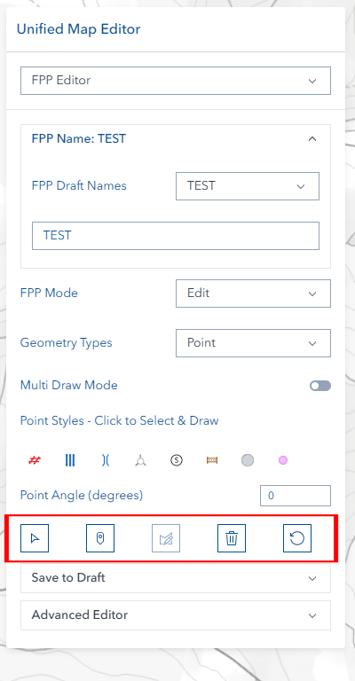
Managing Features
Selecting Features
- Click the Select button (requires layer name)
- Click any FPP feature on the map
- Feature information loads into the editor
- Current style is detected and displayed
Editing Features
- Select a feature first
- Click the Edit button (Edit mode only)
- Use the editing tools to modify the geometry:
- Move vertices by dragging them
- Add vertices by clicking on edges
- Delete vertices by selecting and pressing Delete
- Move entire features by dragging
- Click Save when finished
Deleting Features
- Select the feature you want to delete
- Click the Delete button (trash icon)
- Confirm when prompted
- The feature is removed and layers refresh automatically
Advanced Features

Multiple (Continuous Drawing) Mode
The Multiple toggle controls whether the drawing tool stays active after each feature is placed.
Multiple OFF (Default):
- Draw one feature, then the tool deactivates
- Click the draw button again to draw another feature
Multiple ON:
- The drawing tool stays active after each feature is completed
- Keep clicking on the map to rapidly create many features
- Click the draw button again or press ESC to stop
INFO
Regardless of Multiple mode, every drawn shape is always saved as a separate feature in the layer.
INFO
Switching the Geometry Type dropdown resets the Multiple toggle to off and clears all unsaved graphics.
Advanced Editor

When you have a layer name set, the Advanced Editor becomes available for complex operations:
- Union: Combine areas together
- Buffer: Create setback zones around features
- Difference: Remove areas from other areas
- Intersection: Find overlapping areas
- Cut: Split features with lines
Authorization Workflow
- Switch to Auth mode
- Select the draft plan you want to authorize
- Enter the production FPP number
- Process the authorization
Variation Workflow
- Switch to Vary mode
- Select the production plan to vary
- Enter a variation name in the required format:
VARorVARfollowed by a number (e.g.VAR,VAR1,VAR2) - The system creates a combined layer name as
{FPPNumber}_{VariationName}(e.g.ABC1234_VAR1) — this must be unique across existing production layers - Make your changes and save
Tips & Troubleshooting
Common Issues
| Problem | Solution |
|---|---|
| Drawing buttons are grayed out | Set a layer name first, and make sure you're in Edit mode |
| Can't select styles | Set a layer name first — styles are disabled until a name is set |
| Authorization option missing | Check that you have Auth mode permissions |
| Revoke option not visible | This feature is for administrators only |
| Label Line or Black Arrow won't save | Enter text in the Display Label field — both styles require a display label |
| Point angle not working | Enter a number between 0–359 degrees |
| FPP Number rejected in Auth | Use format AAA0000 (3 letters + 4 digits), optionally followed by _VAR or _VAR1 |
| Variation name rejected | Must be exactly VAR or VAR followed by a number (e.g. VAR, VAR1, VAR2) — no other characters allowed |
| Variation already exists | The combined name {FPPNumber}_{VariationName} already exists in production — use a different number (e.g. VAR2 instead of VAR1) |
| Filter not showing features | Select a name from the dropdown — typing in the text field does not apply the filter |
| Multiple resets after geometry switch | Switching the Geometry Type dropdown resets the Multiple toggle to off |
Best Practices
- Name consistently: Use clear, descriptive layer names
- Check permissions: Make sure you have access to the mode you need
- Save frequently: Use the save function regularly to avoid losing work
- Review before authorization: Double-check draft plans before making them official