Appearance
Spray Editor
Overview
The Spray Editor is a specialized mapping system designed for spray operation planning, including constraint and exclusion zone documentation. This tool integrates ArcGIS drawing tools with spray-specific workflows, providing comprehensive mapping capabilities with point, line, and polygon geometry support. Features include server-rendered symbology, name-based layer filtering, measurement display, label control, and an integrated Advanced Editor for geometric operations.
Key Features:
- All Geometry Types: Full support for points, lines, and polygons
- Spray-Specific Symbol Library: Dedicated symbols for water points, mixing points, exclusion zones, and constraint areas
- Server-Side Rendering: Styles are rendered from server-defined symbology for consistent display
- Name-Based Filtering: Filter the map display by spray name with a single toggle
- Measurement Display: Real-time length and area measurements while drawing
- Label Control: Toggle labels on/off for all spray data layers
- Text Point Support: Place text labels on the map with configurable font size
- Integrated Advanced Editor: Built-in geometric operations for buffer, union, intersect, and difference
Getting Started
Opening the Spray Editor

- Look for the Unified Editor icon (pencil) on the right toolbar
- Click the icon to open the editor panel
- Select Spray Editor from the editor dropdown at the top
What You Can Do
- Map spray operation areas with exclusion zones and constraint polygons
- Mark water points, mixing points, and sampling locations
- Draw constraint lines for spray boundaries
- Filter the map view to a specific spray operation by name
- Add descriptive labels to spray features
- Export or analyse areas using the integrated Advanced Editor
Layer Management
Setting Up Layer Names
The Spray Layer Name panel (a collapsible accordion at the top) contains all name and filter controls. Before you can start drawing, you need to set a spray layer name:
- Use Dropdown: Select an existing spray name from the Spray Names dropdown
- Type New Name: Enter a new spray layer name directly in the text input field below the dropdown
- Wait for Activation: Drawing tools and style buttons become available once a name is set
The system automatically creates and manages these layers when you provide a layer name:
- Spray Point layer (for point markers and locations)
- Spray Polyline layer (for constraint lines)
- Spray Polygon layer (for exclusion zones and constraint areas)
- Spray Graphics layer (for temporary drawing operations)
Filter by Name
Use the Filter by Name toggle to restrict the map display to features belonging to the currently selected spray name:
- Select an existing name from the Spray Names dropdown
- Toggle Filter by Name on
- Both polyline and polygon layers immediately filter to show only features with that name
- Toggle off to show all features again
WARNING
The filter only responds to names selected from the Spray Names dropdown. Typing a name in the text field below activates the editor for drawing, but does not apply the filter.
TIP
While the filter is on, changing the dropdown selection automatically re-applies the filter to the new name — no need to toggle off and back on.
Geometry Types
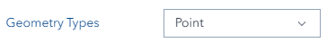
Choose the geometry type that matches what you want to create:
Point Features
- Best for: Water sources, mixing locations, sampling points, text labels
- Examples: Water points, water sample points, mixing points, special markers
Line Features
- Best for: Constraint boundaries, exclusion line features
- Examples: Constraint Line 1 boundaries, Constraint Line 2 boundaries
Polygon Features
- Best for: Exclusion zones, constraint areas
- Examples: No-spray exclusion zones, constraint polygon areas
Style Selection
Choosing Styles
- Set your layer name first (styles are disabled until you do)
- Select your geometry type (Point, Line, or Polygon)
- Click on any style icon to select it
- The selected style will be highlighted with a blue border
Point Styles
| Icon | Style Name |
|---|---|
| Water Point | |
| Water Sample Point | |
| Mixing Point | |
| Special Point | |
| Text Point | |
| Not Coded |
Line Styles
| Icon | Style Name |
|---|---|
| Constraint Line 1 | |
| Constraint Line 2 | |
| Not Coded |
Polygon Styles
| Icon | Style Name |
|---|---|
| Exclusion Zones | |
| Constraint Polygon 1 | |
| Constraint Polygon 2 | |
| Not Coded |
Special Options
Point Angle: For directional point symbols, enter rotation angle (0-359 degrees)
Font Size: For Text Point style only — choose font size from the dropdown (8, 10, 15, 20, 30, 36pt). The font size selector appears automatically when Text Point is selected.
Display Label: Enter an optional text label to attach to any feature when saving.
Drawing Features
Before You Start
- ✅ Set a layer name (from dropdown or by typing)
- ✅ Choose geometry type (Point, Line, or Polygon)
- ✅ Select a style
Toolbar Toggles
Three toggles are available before drawing:
| Toggle | Description |
|---|---|
| Multiple | Enable continuous drawing to create multiple features in one session |
| Measure | Show real-time length (meters) and area (hectares) while drawing |
| Label | Toggle labels on/off for all Spray data layers on the map |
Multiple Mode Drawing
Enable Multiple Mode to create multiple features without repeatedly clicking the draw button. This mode is particularly useful for:
- Marking multiple water points across a spray area
- Drawing several constraint line segments
- Creating multiple exclusion polygon zones in one session
Drawing Steps
For Points:
- Click the Draw Point button (pin icon)
- Click on the map where you want the point
- The point appears immediately
For Lines:
- Click the Draw Line button (line icon)
- Click points along your desired constraint boundary
- Double-click to finish the line (or press ESC to cancel)
For Polygons:
- Click the Draw Polygon button (polygon icon)
- Click points around your exclusion or constraint area
- Double-click to close the polygon (or press ESC to cancel)
Visual Feedback
- Draw buttons highlight when active
- Active drawing button switches to a filled appearance in continuous mode
- Disabled buttons show helpful tooltips explaining what is needed
Feature Information
When you save features, the system automatically records:
- Spray layer name
- Display label (if provided)
- Style type ID for server-side symbology
- Point angle (for point features)
- Font size (for Text Point features)
- Username for tracking
- Object ID for editing and deletion
- Area in hectares (polygon features only) — calculated automatically by the server at save and refreshed when the polygon is edited; visible in the Spray Polygon attribute table
Managing Features
Selecting Features
- Click the Select button (cursor/select icon) — requires a layer name to be set
- Click any spray feature on the map
- Feature information loads into the editor (style, name, label, angle)
- Click the same location again to cycle through overlapping features
Editing Features
- Select a feature first
- Click the Edit button (edit-geometry icon)
- Use the reshape tool to modify the geometry:
- Move vertices by dragging them
- Add vertices by clicking on edges
- Delete vertices by selecting and pressing Delete
- Move entire features by dragging
- Expand the Save to Spray accordion (collapsed by default) and click Save to write changes back to the server
TIP
The Save to Spray section is collapsed by default. Click its heading to expand it before saving.
Deleting Features
- Select the feature you want to delete
- Click the Delete button (trash icon)
- The feature is removed from the map and database
- Layers refresh automatically after deletion
Resetting / Clearing
Click the Reset button (reset icon) to:
- Clear all temporary graphics from the drawing canvas
- Deactivate any active drawing or selection mode
- Reset the editor ready for a new operation
Advanced Features
Multiple (Continuous Drawing) Mode
The Multiple toggle controls whether the drawing tool stays active after each feature is placed.
Multiple OFF (Default):
- Draw one feature, then the tool deactivates
- Click the draw button again to draw another feature
Multiple ON:
- The drawing tool stays active after each feature is completed
- Keep clicking on the map to rapidly create many features
- Click the draw button again or press ESC to stop
INFO
Regardless of Multiple mode, every drawn shape is always saved as a separate feature in the layer. All geometry types (points, lines, and polygons) are fully supported in Multiple mode.
INFO
Switching the Geometry Type dropdown cancels active drawing and clears all unsaved graphics. The Multiple toggle stays on — turn it off manually if you no longer want continuous drawing after switching types.
Advanced Editor

When a layer name is set, the Advanced Editor becomes available for complex geometric operations:
- Union: Combine multiple spray areas into one unified zone
- Buffer: Create setback or safety buffer zones around features
- Difference: Subtract one area from another to create exclusion shapes
- Intersection: Find overlapping areas between spray zones and constraints
- Cut: Split features using cutting lines
INFO
The Advanced Editor is disabled until a layer name is entered.
Practical Applications
Buffer Operations: Create buffer zones around:
- Water sources and mixing points
- Sensitive environmental areas requiring exclusion buffers
- Property boundaries for no-spray zones
Difference Operations: Remove areas from larger spray zones:
- Carve out wildlife habitat exclusion areas
- Subtract cultural heritage or infrastructure zones
- Define specific no-spray corridors
Union Operations: Merge multiple constraint polygons:
- Combine adjacent exclusion zones into a single boundary
- Merge overlapping constraint areas for simplified geometry
Tips & Troubleshooting
Common Issues
| Problem | Solution |
|---|---|
| Drawing buttons are grayed out | Set a layer name first — either select from dropdown or type a new name |
| Style icons not clickable | Enter a layer name first to enable style selection |
| Cannot select features | Ensure a layer name is set; click directly on a visible spray feature |
| Feature cycles on repeated clicks | Click the same location again to cycle through overlapping features |
| Edit mode not working | Select a feature first, then click the Edit button |
| Save fails | Check that at least one graphic is drawn and a layer name is provided |
| Font size not appearing | Select Text Point style — font size is only shown for Text Point |
| Label toggle has no effect | Spray layers must be loaded first; set a layer name and draw a feature |
| Filter by Name shows nothing | Select a spray name from the dropdown before enabling the filter toggle |
| Not Coded features cannot be drawn | Not Coded is a display-only fallback; select a named style to draw features |
| Layer name too long | Spray layer names must be 50 characters or fewer |
| Advanced Editor disabled | Enter a layer name to enable the Advanced Editor |
Best Practices for Spray Mapping
- Name clearly: Use descriptive, consistent spray operation names
- Start with exclusions: Map exclusion zones first, then add point locations
- Use Filter by Name: When working on a specific operation, enable the name filter to reduce visual noise
- Measure as you draw: Enable the Measure toggle for accurate area and length tracking
- Label key features: Use the Display Label field or Text Point style for important markers
- Apply Text Point for annotations: Use Text Point with an angle for directional labels
Working with Text Point
- Select the Text Point style (point geometry type)
- Enter display text in the Display Label field (in Save section)
- Choose font size from the font size dropdown (8, 10, 15, 20, 30, 36pt)
- Optionally set a Point Angle (0-359°) for directional orientation
- Click Draw Point and place on the map
- Click Save to commit
Working with Point Angles
- Select any rotatable point style
- Enter angle in degrees (0-359) in the Point Angle field
- 0° faces east, 90° faces north, 180° faces west, 270° faces south
- Angle is stored with the feature and restored when re-selecting it
INFO
The Point Angle field resets to 0° whenever you switch to a different Geometry Type and back. If you have a specific angle in mind, set it again after switching.