Appearance
Map Editor Tool
Overview
The Map Editor Tool is a comprehensive spatial editing system that provides professional-grade geometric creation, modification, and spatial analysis capabilities. This sophisticated tool integrates ArcGIS drawing tools with advanced spatial operations, offering multiple geometry types, intelligent snapping systems, complex spatial analysis functions, and export capabilities optimized for professional GIS workflows and spatial data management applications.
A typical session follows four steps:
- Create features — draw, select, or add them by coordinates, using the drawing options to control how they are drawn.
- Combine and split them against a second set of shapes, or reshape them with the shape tools.
- Step back with Undo, Redo and Reset whenever something goes wrong.
- Export or save the result as a file or a personal MyLayer.
Opening the Editor
- Locate Map Editor Icon
- Click to open editor panel

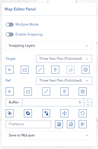
Panel Layout
The panel reads top to bottom in the order you work:
| Area | What it holds |
|---|---|
| Drawing options row | The Multi, Snap and Meas switches and the Line style picker |
| Target row | Target layer dropdown, Select, the Polygon / Line / Point draw buttons, Edit and Buffer |
| Ref (reference) row | Ref layer dropdown, the same Select / draw / Buffer buttons, and the shared Buffer distance input |
| Undo / Redo / Reset row | Panel-level history controls |
| Operation groups | Three collapsible groups of operation buttons |
| Export / Save tabs | The last step — download a file or save a MyLayer |
Target and Reference Layers
The editor works with two graphics layers. The target layer holds the shapes you are building; the Ref (reference) layer holds a second set of shapes used as input to the Combine & Split operations. The shape tools and both export paths use the target layer only.
Operation Groups
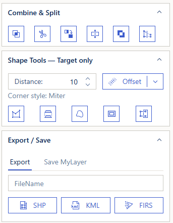
The operation buttons are organised into three collapsible groups, so it is clear what each one needs as input:
| Group | Needs | Contains |
|---|---|---|
| Combine & Split | Target and Reference shapes | Intersect, Cut Shape, Merge Shape, Split Shape, XOR, Reshape |
| Shape Tools — Target only | Target shapes only | Offset, Simplify, Explode, Hull, To Lines, To Polygons |
| Export / Save | Finished shapes | SHP, KML, FIRS, Save MyLayer |
Export / Save is the last step of the workflow, so it starts collapsed. Hover any button in a group to see its tooltip.
Creating Features
Drawing Tools
Available geometry types:
- Polygon:

- Line:

- Point:

Drawing steps:
- Select geometry type
- Click map to draw
- Double-click to complete
Selecting Existing Features

- Choose layer from dropdown
- Click 'Select' button
- Click layer on map
- Click 'Select' again to deactivate
Adding a Point from Coordinates
Instead of clicking the map, you can place a point at an exact location:
- Enter X / Easting and Y / Northing (GDA94 / MGA Zone 55, EPSG:28355)
- Click the add button
Coordinates must fall inside Tasmania (Easting 190,000–640,000, Northing 5,120,000–5,630,000); anything outside that range is rejected with a message rather than placed off-map.
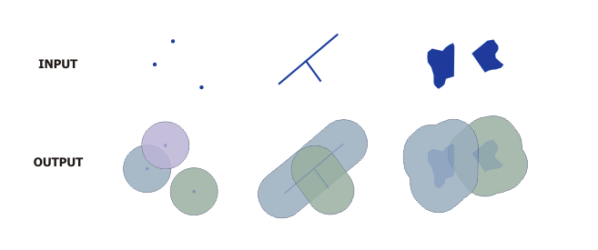
Buffering a Shape
Both the target and the reference row have a Buffer button, and they share the Buffer distance input:
- Enter buffer distance
- Click buffer button


One Geometry Type at a Time
The editor holds one geometry type at a time, because both export and Save to MyLayer handle a single type. If you already have shapes of one type and start adding another — arming a different draw tool, selecting a feature of another type, or adding a point by coordinates — a Remove Existing Shapes? dialog appears first:
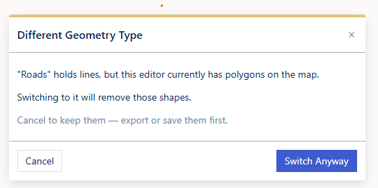
- Remove and Continue — clears the existing shapes and proceeds. The clear is recorded, so Undo brings them back.
- Cancel — nothing is removed and whatever you had armed or selected stays as it was.
Switching the Target or Ref dropdown to a layer of a different geometry type asks in the same way before clearing.
Drawing Options

Above the drawing buttons is a row of drawing options: three switches — Multi, Snap and Meas — and the Line style picker. The switch labels are abbreviated so all four controls fit on one line in a narrow panel; hover any of them to see a tooltip with the full meaning. On a narrow panel or a small screen the row wraps onto a second line rather than hiding anything.
Multi — Continuous Drawing
Enable continuous drawing by toggling the Multi switch. When active, completing a feature (point, line, or polygon) automatically re-initiates the same drawing tool, allowing you to draw the next feature immediately without re-clicking the draw button. Toggle the switch off to return to single-draw mode.
Snap — Snapping to Features
Turn on the Snap switch to snap to features while drawing. A Snapping Layers list appears below the row so you can choose which layers to snap to.
The editor includes a sophisticated snapping system that:
- Enables precise feature alignment
- Supports multiple layer snapping sources
- Provides real-time snapping feedback
- Maintains accuracy during digitization
Meas — Real-Time Measurement Display
Toggle the Meas switch to display live measurements while drawing:
- Polygons: Shows area in hectares (ha) and square metres (m²) at the polygon centroid
- Polylines: Shows length in metres (m), automatically converting to kilometres (km) at 1,000 m or above
- Measurements update in real-time as you add vertices or edit shapes
- A final measurement label persists on the completed feature
- Calculations use geodetic (curved-earth) measurement for accuracy
INFO
Measurement operators are lazy-loaded when you first enable the Measure toggle, so there may be a brief delay on first activation.
Line Style — Straight or Arc
The Line style picker at the end of the drawing options row controls how the line tool reads your clicks. It has two icon buttons:
| Style | Icon | How your clicks are read |
|---|---|---|
| Straight (default) | straight line | Every click is a vertex, joined by straight segments — the long-standing behaviour. |
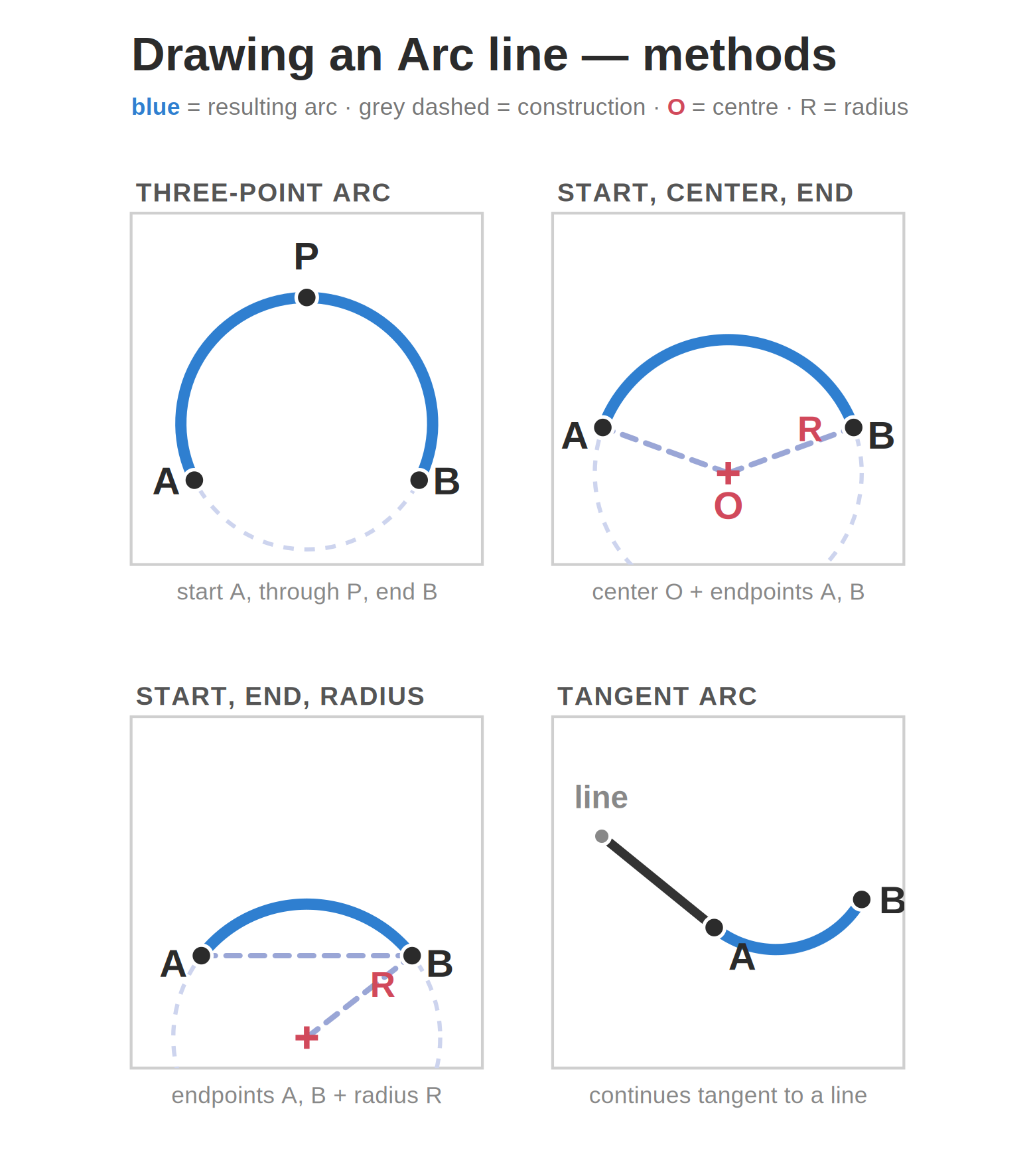
| Arc | curved segment | Clicks are read as a chain of curves: the first click starts the line, then each pair of clicks is a point to curve through followed by the end point of that curve. |
While Arc is selected, a reminder line appears under the row:
Arc: click a start point, then a point to curve through and an end point — repeat the last two for each further curve.
Drawing an arc:
- Set the line style to Arc
- Click the line tool
- Click the start point
- Click a point the curve should pass through, then click the curve's end point
- Repeat step 4 for each further curve — each new curve continues from the previous end point
- Double-click to complete the line
The curve appears live as you click, so you can see the shape before finishing. Three clicks give one curve, five clicks give two joined curves, and so on.
Arc lines behave like any other line
A finished arc is stored as a closely-followed series of vertices (accurate to within about 0.25 m of the true curve), so everything else works normally — measurement, the shape tools, spatial operations, Reset, export to SHP/KML/FIRS, and Save to MyLayer. Nothing downstream has to be done differently.
Notes
- The line style applies to lines only — points and polygons are unaffected.
- It governs both the target and the reference line tools, and works with Multi, Snap and Meas.
- Your choice stays selected between draws, so you can draw several arc lines in a row. It also stays selected if you close and reopen the editor — it returns to Straight only when you reload Horizon. If a line comes out curved when you expected it straight, check this picker first.
When a curve stays straight
A curve needs a genuine bend. If the middle (through) click sits almost on the straight line between the start and end points, or beyond the end point, that piece is drawn as straight segments instead — this prevents an accidental click from producing a huge unintended sweep. Place the middle click clearly to one side, and between the start and end points.
If you finish with an odd number of clicks left over, the last unpaired click is joined as a straight segment.
Combine & Split
The Combine & Split group holds the six operations that use the shapes on the target layer together with the shapes on the reference layer. The buttons show icons only, so hover one to see its name.
If you learned the older button names
Three of these buttons were renamed to say plainly what they do. The operations themselves are unchanged — the same button does the same thing, only the wording on the tooltip is different.
| You used to hover | It now reads | What it does |
|---|---|---|
| Subtract | Cut Shape | Removes the reference shapes from the target shapes |
| Union | Merge Shape | Combines the shapes into one |
| Cut | Split Shape | Splits a target polygon along a reference line |
Take particular care with Cut: it used to mean "split a polygon with a line", and that is now Split Shape. Cut Shape is the old Subtract. Two of the button icons changed at the same time, so the row may not look quite the way you remember it either.
Available Operations
Each button is named below exactly as its tooltip reads:
| Button | What it does |
|---|---|
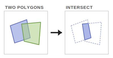
| Intersect Shape | Keeps only the area covered by both the target and the reference shapes. |
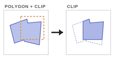
| Cut Shape | Removes the reference shapes from the target shapes (the difference between them). |
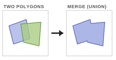
| Merge Shape | Combines the target shapes into one. Reference shapes are merged in as well when the reference layer holds any; any that are not the same geometry type as the target are left out, and a note tells you how many. |
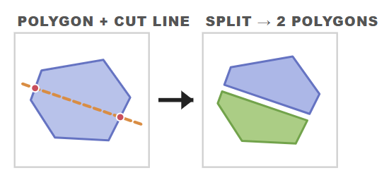
| Split Shape | Splits the target polygons along a reference line. |
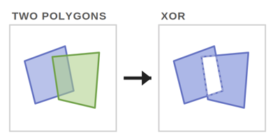
| XOR Shape (symmetric difference) | Keeps the parts covered by the target or the reference shapes, but not both. Target and reference must be the same geometry type. |
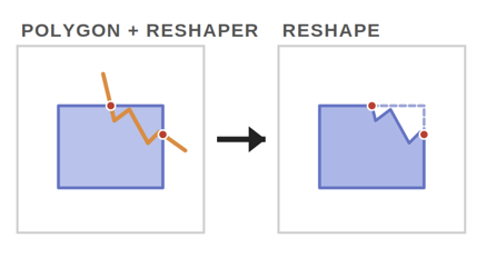
| Reshape Shape (draw a Ref line across it) | Redraws part of a target polygon or line to follow a line you draw in the reference layer. |
Intersect

Cut Shape

Merge Shape

Split Shape

XOR

Reshape

Using Split Shape
- Draw or select the polygon(s) you want to divide in the target layer
- Draw or select a line in the reference layer that crosses them
- Click Split Shape
Split needs at least one polygon on the target layer and at least one line on the reference layer; if either is missing, the tool says so rather than doing nothing.
Using Reshape
- Draw or select the polygon(s) or line(s) you want to change in the target layer
- Draw one continuous line in the reference layer that crosses the target shape
- Click Reshape
The target shape's boundary is re-routed to follow the reference line, and the reference layer is cleared.
WARNING
Reshape needs exactly one reference line with a single unbroken path. If the reference layer holds more than one line — or a line drawn in separate pieces — the tool reports that it needs a single continuous line. If the line does not actually cross a target shape, nothing is reshaped.
Using XOR
- Draw or select the target shape(s)
- Draw or select the reference shape(s) — they must be the same geometry type as the target
- Click XOR
The result is everything covered by one set or the other, with the shared overlap removed. If the two sets cover exactly the same area, nothing remains and the tool reports this instead of clearing your work.
Shape Tools
The Shape Tools — Target only group holds the tools that reshape, tidy up, or restructure the geometry already on the target layer — no reference layer is involved. Every tool replaces the target shapes with its result — the same read-and-replace behaviour as Merge Shape and Buffer — so you can chain tools one after another, step back with Undo, or use Reset to start again.
Hover any button to see its tooltip.
| Tool | What it does |
|---|---|
| Offset | Shifts target lines and polygons sideways by the signed Distance value, using the selected corner style. |
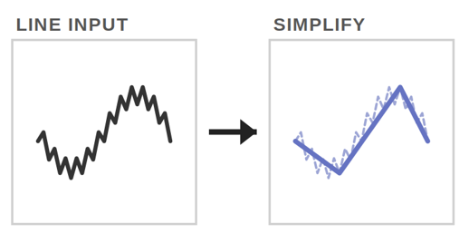
| Simplify | Removes surplus vertices from target polygons/lines, using the Distance value as the maximum allowed deviation. |
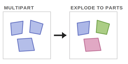
| Explode | Splits multipart shapes into one separate shape per part. |
| Hull | Replaces all target shapes with the single convex hull (the tightest enclosing boundary) around them. |
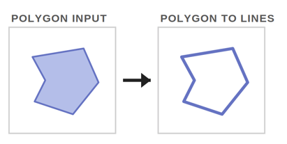
| To Lines | Converts target polygons into boundary lines — each ring becomes a line. See conversion notes. |
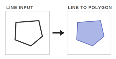
| To Polygons | Converts target lines into polygons, filling the areas they enclose. See conversion notes. |
Explode
TIP
XOR and Reshape are shape-changing tools too, but they live in the Combine & Split group because they also need the reference layer.
The Distance Input
Simplify and Offset both read the shared Distance field (in metres) that sits on the same line as the Offset button:
- Simplify uses the absolute value as the maximum deviation — a larger number removes more vertices.
- Offset uses the signed value:
- Line — a positive distance offsets to the right of the line's drawn direction, a negative distance to the left.
- Polygon — a positive distance expands the polygon outwards, a negative distance contracts it inwards.
Offset is not the same as Buffer
Buffer always grows a shape outwards in every direction and turns a line into a polygon. Offset shifts a shape sideways and keeps a line as a line, so it is the tool to use for parallel tracks, road setbacks, or shrinking a polygon slightly.
Offset Corner Style
Offset is a split button: the left half runs the offset, and the arrow on the right picks how corners are treated. The active choice is shown underneath as Corner style: …, and it stays selected between offsets.
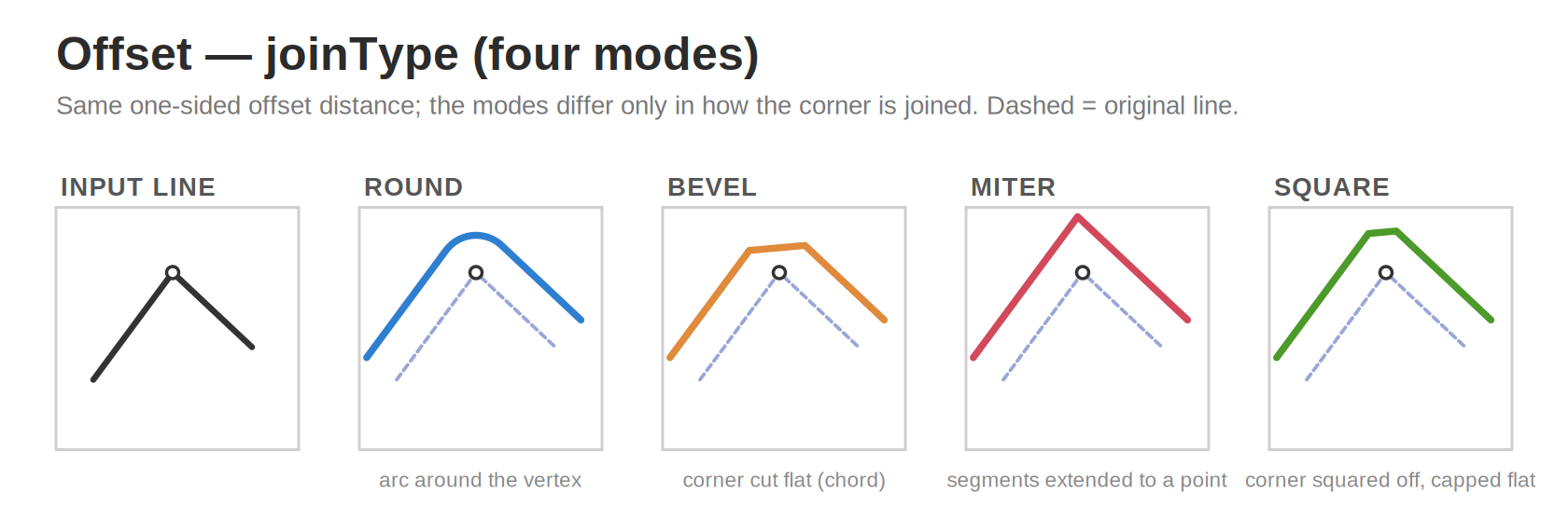
| Corner style | Result |
|---|---|
| Miter (default) | Sharp corners, extended to a point. Very acute corners are trimmed automatically instead of spiking. |
| Round | Corners are rounded off with a smooth arc. |
| Bevel | Corners are cut off with a straight edge. |
| Square | Corners are squared off. |
If an offset is refused
Offsetting a polygon inwards repeatedly eventually collapses it on itself. When that happens — or when a result would become excessively complex — the shape is left as it was and the message reports how many shapes could not be offset, so a further click cannot progressively mangle your geometry.
Converting Between Lines and Polygons
- To Lines needs at least one polygon on the target layer. Each polygon's rings become boundary lines, and the polygons are replaced by them.
- To Polygons needs lines on the target layer and works on all of them at once, filling every enclosed area. A hand-drawn loop rarely ends exactly on its start point, so a nearly-closed line is closed for you before the conversion; a clearly open line (a V, an out-and-back) is left alone rather than having area invented for it. If nothing is enclosed, the tool says so and your lines are kept.
Notification Messages
Each shape tool reports what it did, for example:
- "Reshaped 2 shapes"
- "Exploded 1 multipart shape into 4 shapes"
- "Simplified: 412 vertices down to 96"
- "Offset 3 shapes successfully"
- "Converted 2 polygons to boundary lines"
If a tool cannot run, the message explains why — for example "Enter a non-zero distance in meters", "Offset works on lines and polygons — draw or select one in the target layer", or "No multipart shapes to explode".
Undo, Redo and Reset
The row above the operation groups holds Undo, Redo and Reset. They act on the editor as a whole and stay available even if the selected target layer disappears from the map.
- Undo steps back through your operations — draws, selections, buffers, spatial operations, shape tools, and the clear that happens when you switch layers or press Reset. Up to 20 steps are kept.
- Redo steps forward again. Undo and Redo are greyed out when there is nothing to step through.
- Reset clears both the target and reference layers — and is itself undoable, so an accidental Reset can be recovered with Undo.

"Nothing to Redo"
If you undo something and then make a new change, the redo history no longer applies and a short Nothing to Redo notice explains why the button stopped working. Redoing after finishing a shape edit does the same — the completed edit starts a new step.
Export and Save
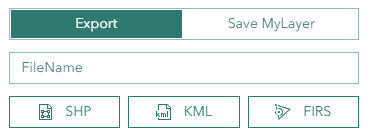
The bottom of the panel has two tabs — Export and Save MyLayer. The Export tab is selected by default, and switching between the two tabs does not lose what you have typed in the other.
Format Options
- SHP — Exports drawn geometry as a Shapefile in the map's native projection (GDA94 / MGA Zone 55).

- KML — Exports drawn geometry in KML format.

- FIRS — Exports drawn geometry as a Shapefile reprojected to WGS 84 (EPSG:4326) coordinates, formatted for import into the Fire Incident Reporting System (FIRS). Use this option when you need to submit spatial data to FIRS.

Exporting a File
Optional: Enter filename
Click the desired export button (SHP, KML, or FIRS)
Saving to a MyLayer
Instead of downloading a file, you can keep the geometry in Horizon as a personal layer:
- Switch to the Save MyLayer tab
- Enter a MyLayer Name — this identifies the layer and must be unique among your own layers
- Enter a Display Label — the name shown on the map and in the layer list
- Click Save
The saved layer then appears in the My Layers Tool, where you can show, style, or export it later.
INFO
If the MyLayer name is already in use, the Name Already Exists dialog asks whether to replace the existing layer.
Overlapping Geometry Detection
Before your shapes are written to a file or saved to a MyLayer, the editor checks whether any of them overlap each other at the same location — for example the same polygon drawn twice, or two lines sharing a segment. This catches the common mistake of exporting duplicated or stacked geometry without noticing.
If an overlap is found, an Overlapping Geometry Detected dialog appears and pauses the export/save until you choose how to proceed.
What counts as an overlap:
- Polygons whose intersection has real area (edge-touching polygons are not flagged).
- Lines that share a segment (lines that merely cross at a single point are not flagged).
- Points that sit at the same location (coincident duplicates).
Only like-with-like shapes are compared, so a point is never treated as overlapping a polygon or a line.
Dialog choices:
- Merge — combines each overlapping group into a single feature. Non-overlapping shapes are left unchanged.
- Keep Separate — proceeds with every shape exactly as drawn, overlaps included.
- Cancel — stops the export/save so you can go back and edit the shapes.
INFO
The overlap check applies to all export formats (SHP, KML, FIRS) and to Save to MyLayer. If no overlaps are detected, the dialog does not appear and the export/save continues as normal.
Name Already Exists Dialog
When saving geometry to a MyLayer name that already exists, a warning dialog appears to prevent accidental overwrites.
Dialog Details:
- Heading: "Name Already Exists"
- Kind: Warning (yellow indicator)
- Modal: Yes — you must respond before continuing
- Content: Displays the existing layer name and geometry type, and asks whether to replace the existing layer with the new geometry
- Footer Buttons:
- Cancel (left) — closes the dialog without changes
- Replace (right) — overwrites the existing MyLayer with the new geometry
The dialog prevents closing via the Escape key or clicking outside, ensuring you make an explicit choice.
Exporting a Saved MyLayer
To export previously saved MyLayers to Shapefile or KML format, use the export options in the My Layers Tool. Each saved layer has an export dropdown with Export as SHP and Export as KML options.
Troubleshooting
Drawing and Selecting
| Issue | Solution |
|---|---|
| Layer selection fails | Check layer visibility |
| Operation errors | Verify geometry validity |
| Coordinates rejected when adding a point | X/Y must be GDA94 MGA Zone 55 metres inside Tasmania (Easting 190,000–640,000, Northing 5,120,000–5,630,000) |
| "Remove Existing Shapes?" keeps appearing | The editor holds one geometry type at a time; finish and export/save the current shapes, or choose Remove and Continue |
| Drawing options row is on two lines | Expected on a narrow panel or small screen — widen the browser window, or the panel, to fit Multi / Snap / Meas and Line style on one line |
| Arc line style draws straight segments | The middle (through) click was almost on the line between the start and end points, or past the end point — click it clearly to one side and between them |
| Only part of my arc line is curved | Each curve needs two clicks after the start (through, then end); a leftover unpaired click is joined as a straight segment |
| Line style picker has no effect | It applies to the line tool only — points and polygons always draw as before |
Combine & Split
| Issue | Solution |
|---|---|
| I cannot find Subtract or Union | They were renamed — Subtract is now Cut Shape and Union is now Merge Shape. Nothing about what they do has changed |
| Cut Shape did not split my polygon along a line | Cut Shape removes the reference shapes from the target. To divide a polygon with a line, use Split Shape |
| Cut Shape says nothing remains after the cut | The reference shapes cover the whole target, so there is nothing left to keep — Undo, then make the reference shape smaller |
| Merge Shape says some reference shapes were skipped | Merge only takes reference shapes of the same geometry type as the target; the rest are left out |
| Split Shape says it needs a polygon, or needs a polyline | Split needs at least one polygon on the target layer and at least one line on the reference layer |
| Reshape says it needs a single continuous line | The reference layer must hold exactly one line drawn in one unbroken run; press Reset and draw it again |
| Reshape reports "does not cross any target shape" | The reference line must cross the target boundary, not merely sit near or inside it |
| XOR reports a type mismatch | Target and reference must both be polygons, both lines, or both points |
Shape Tools
| Issue | Solution |
|---|---|
| Simplify reports no vertices removed | Increase the Distance value — the current deviation is too small to drop any vertices |
| Offset or Simplify says "Enter a non-zero distance" | The Distance field is empty or 0; enter a value in metres (use a negative value to offset the other way) |
| Offset went the wrong way | Reverse the sign of Distance — for polygons + expands and − contracts, for lines + is right of the drawn direction |
| Offset corners are not the shape I expected | Use the arrow on the Offset button to pick Round, Miter, Bevel or Square; the active choice is shown as Corner style: … |
| Offset reports shapes it could not offset | A polygon contracted past the point where it collapses, or the result became too complex — the shapes are left unchanged |
| Hull reports it could not build a hull | The shapes are all in a straight line or at a single point; a hull needs shapes spread over an area |
| To Lines says it needs a polygon | The tool converts polygons to boundary lines — draw or select a polygon on the target layer first |
| To Polygons says the lines enclose no area | The lines must close a loop (a nearly-closed loop is closed for you, but an open line is not) |
Undo, Redo and Reset
| Issue | Solution |
|---|---|
| Undo or Redo is greyed out | There is nothing left to step through in that direction; only the last 20 steps are kept |
| Redo stopped working after an edit | Making a new change discards the redo history — the Nothing to Redo notice explains this |
Export and Save
| Issue | Solution |
|---|---|
| Export issues | Check geometry complexity |
| Export fails | Ensure MyLayer has valid geometry data |
| No features exported | Check that MyLayer contains features in the database |
| MyLayer not in export list | Verify MyLayer was saved under your username |
| Overlap dialog keeps appearing | Expected when shapes overlap — choose Merge to combine them, Keep Separate to export as-is, or Cancel to edit |
Video Tutorials
INFO
Some of these clips were recorded before the operation buttons were renamed, so the wording on screen may differ from the names used above. The steps and the results are the same.
Snapping Operation
Intersection Operation
Cut Shape Operation
Merge Shape Operation
Split Shape Operation
Buffer Operation
Shape File Export
KML Export
See Also
- Advanced Editor - Standalone geometric operations (buffer, union, intersect, difference, reshape, hull)
- My Layers Tool - Manage personal map layers created with the Map Editor
- Unified Map Editors - Specialised editors for FPP, Plan Burn, Sketch, and other workflows