Appearance
Sketch Tool
Table of Contents
- Overview
- Getting Started
- Layer Management
- Geometry Types
- Style Selection
- Drawing Features
- Managing Features
- Advanced Features
- Tips & Troubleshooting
- Video Tutorials
Overview
The Sketch Tool is a sophisticated general-purpose spatial editing system designed for versatile mapping, annotation, and visual communication applications. This powerful tool integrates ArcGIS SketchViewModel technology with comprehensive drawing capabilities, providing professional-grade sketching functionality with multiple geometry types, extensive style libraries, user-specific layer management, and advanced geometric operations for flexible spatial data creation and annotation workflows.
Key Features:
- Comprehensive Geometry Support: Three primary geometry types (points, lines, polygons) with 15+ specialized style options
- User-Specific Layer Management: Personal sketch layer system with automatic user attribution and data isolation
- Advanced Drawing Tools: ArcGIS SketchViewModel integration with coordinate transformation and spatial reference handling
- Extensive Style Library: Professional icon collection including landing, crossing, helicopter, hazard, and custom sketch symbols
- Integrated Advanced Editor: Built-in geometric operations for buffer, union, intersect, and difference operations
- Flexible Annotation System: Text line support with configurable font sizes and labeling capabilities
- Multiple Mode Support: Single and multiple feature drawing modes for enhanced productivity
Getting Started
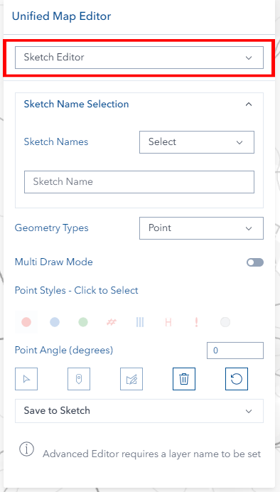
Opening the Sketch Tool

- Look for the Unified Editor icon (pencil) on the right toolbar
- Click the icon to open the editor panel
- Select Sketch mode from the mode selector at the top
What You Can Do
- Create personal sketches and annotations
- Mark areas of interest and important locations
- Draw temporary planning features
- Create visual aids for communication
- Annotate maps with text and symbols
Your sketch data is personal - each user has their own sketch layers that don't affect other users.
Layer Management
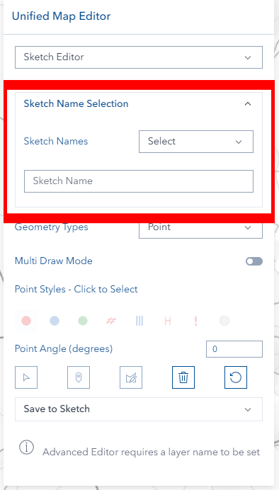
Setting Up Layer Names
Before you can start drawing, you need to set a layer name:
- Use Dropdown: Select an existing sketch layer name from the list
- Type New Name: Enter a new sketch layer name in the text field
- Wait for Activation: Drawing tools become available once a name is set
The system automatically creates these layers when you provide a layer name:
- Sketch Point layer (for point markers and locations)
- Sketch Polyline layer (for lines, boundaries, and paths)
- Sketch Polygon layer (for areas, zones, and regions)
- Sketch Graphics layer (for temporary drawing operations)
Geometry Types
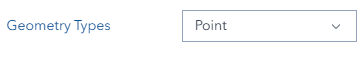
Choose the geometry type that matches what you want to create:
Point Features
- Best for: Locations, markers, landmarks, points of interest
- Examples: Equipment locations, meeting points, hazard markers, photo locations
Line Features
- Best for: Paths, boundaries, routes, connections, annotations
- Examples: Walking routes, property boundaries, flow directions, measurement lines
Polygon Features
- Best for: Areas, zones, regions, boundaries
- Examples: Work areas, zones of interest, exclusion areas, planning regions
Style Selection
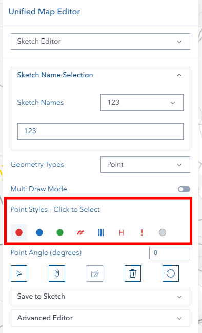
Choosing Styles
- Set your layer name first (styles are disabled until you do)
- Select your geometry type (Point, Line, or Polygon)
- Click on any style icon to select it
- The selected style will be highlighted
Point Styles
| Icon | Style Name |
|---|---|
| Sketch Point Style 1 | |
| Sketch Point Style 2 | |
| Sketch Point Style 3 | |
| Landing | |
| Cross | |
| Helicopter | |
| Hazard | |
| Label Box |
Line Styles
| Icon | Style Name |
|---|---|
| Sketch Line Style 1 | |
| Sketch Line Style 2 | |
| Sketch Line Style 3 | |
| Black Arrow | |
| Text | |
| Tracking width (5m) | |
| Tracking width (10m) | |
| Single blade width or existing track repair |
Polygon Styles
| Icon | Style Name |
|---|---|
| Sketch Polygon Style 1 | |
| Sketch Polygon Style 2 | |
| Sketch Polygon Style 3 | |
| Remedial Areas | |
| Tracking width (5m) | |
| Tracking width (10m) | |
| Single blade width or existing track repair |
Special Options
Point Angle: For rotatable point symbols, enter rotation angle (0-359 degrees)
Text Options: For Text line style, enter display label and choose font size (8-72pt)
Drawing Features
Before You Start
- ✅ Set a layer name
- ✅ Choose geometry type
- ✅ Select a style
Multiple Mode Drawing
Enable continuous drawing to create multiple features without repeatedly clicking draw buttons. This mode allows rapid digitization of complex geometries and multiple feature creation.
Drawing Steps
For Points:
- Click the Point draw button
- Click on the map where you want the point marker
- The point appears immediately
For Lines:
- Click the Line draw button
- Click points along your desired path or boundary
- Double-click to finish the line
For Polygons:
- Click the Polygon draw button
- Click points around your area
- Double-click to close the polygon
Visual Feedback
- Draw buttons light up when active
- Disabled buttons show helpful tooltips
- Features appear on the map as you draw them
Feature Information
When you save features, the system automatically records:
- Layer name
- Display label (if provided)
- Style attributes
- Username for tracking
- Creation timestamp
Managing Features
Selecting Features
- Click the Select button (requires layer name)
- Click any sketch feature on the map
- Feature information loads into the editor
- Current style is detected and displayed
Editing Features
- Select a feature first
- Click the Edit button
- Use the editing tools to modify the geometry:
- Move vertices by dragging them
- Add vertices by clicking on edges
- Delete vertices by selecting and pressing Delete
- Move entire features by dragging
- Click Save when finished
Deleting Features
- Select the feature you want to delete
- Click the Delete button (trash icon)
- Confirm when prompted
- The feature is removed and layers refresh automatically
Advanced Features

Multi-Draw Mode
Toggle between two drawing behaviors:
Single Mode (Default):
- Draw multiple shapes
- They combine into one feature when saved
- Good for complex areas made of multiple parts
Multi Mode:
- Draw multiple shapes
- Each becomes a separate feature when saved
- Good for creating multiple similar features quickly
Advanced Editor

When you have a layer name set, the Advanced Editor becomes available for complex geometric operations:
- Union: Combine multiple areas into one
- Buffer: Create buffer zones around features
- Difference: Subtract one area from another
- Intersection: Find overlapping areas between features
- Cut: Split features using cutting lines
- Simplify: Reduce geometry complexity while preserving shape
Practical Applications
Union Operations: Combine multiple sketch areas into single zones for planning
Buffer Operations: Create setback zones around:
- Points of interest
- Hazard areas
- Equipment locations
Difference Operations: Remove areas from larger zones:
- Exclude sensitive areas from work zones
- Create complex boundary shapes
Intersection Analysis: Find overlaps between:
- Different sketch layers
- Planning areas and constraints
Layer Organization
- Personal Data: Each user has their own sketch layers
- Automatic Groups: Sketch layers organized in "Sketch Layers" group
- Graphics Layers: Temporary drawing layers in "Sketch Graphics" group
- Persistence: Your sketch data remains available across sessions
Tips & Troubleshooting
Common Issues
| Problem | Solution |
|---|---|
| Drawing buttons are grayed out | Set a layer name first in the dropdown or text field |
| Can't select features | Ensure layer name is set and target features exist |
| Edit mode not working | Select a feature first, then click Edit button |
| Save failures | Check that geometry is complete and layer name is provided |
| Style buttons not clickable | Set layer name first to enable style selection |
| Text line won't save | Enter text in the Display Label field for Text style |
| Angle input not working | Enter a number between 0-359 degrees for point rotation |
Best Practices for Sketching
- Use descriptive names: Give your sketch layers meaningful names
- Organize by purpose: Create separate layers for different types of sketches
- Consider colors: Different styles help distinguish between feature types
- Add labels: Use the Text line style or Label Box points for annotations
- Clean up regularly: Delete temporary sketches you no longer need
Working with Text Features
- Select the Text line style
- Enter your text in the Display Label field
- Choose font size from the dropdown (8-72pt)
- Draw the line where you want the text to appear
- Text will render along the line path
Working with Point Angles
- Select a rotatable point style
- Enter angle in degrees (0-359) in the angle field
- 0° points east, 90° points north, 180° points west, 270° points south
- Useful for directional markers and oriented symbols